GMA-VM-FMS Remote alarm system
Monitors district-heating manhole facilities and technical rooms:
detects heat build-up and fire
Application: for monitoring district-heating manhole facilities & technical rooms
- Immediately after the set temperature is reached (57°C, 68°C or 79°C) the thermobulb, which functions as a signal generator (e.g. in sprinkler system), bursts inside the signal generator casing, thereby activating the compression spring. The spring expands and activates the push-pull signal transmitter, which passes the mechanical signal on to the sensor.
- After the heat has been dissipated and the whole signal generator (casing, compression spring and thermobulb) has been replaced, the sensor can be used again. In the event of fire, the sensor and the push-pull signal transmitter must be replaced too.
Particular features:
- Various states, e.g. opening, heat build-up, water level etc. can be monitored simultaneously, by setting up the appropriate EMA-VM and GMA-VM remote alarm systems in series. If a GMA-VM is triggered at a temperature range < 80°C, the respective remote alarm can be re-set to alert within 3 minutes after the cause has been removed and the signal generator replaced.
- When several remote alarms are in use, the precise location of the alarm for water, heat/fire or unauthorised entry is made possible if a dead-zone box (with dead-zone fibres) is utilised.

Key
No. | Designation | Art. No. |
[1] | VM cable (connection to a distribution module) | 49.04 GMA-VM-TO (1 x GMA sensor + TO dead-zone box)
50.29 GS-FMS* Signal generator with signal transmitter |
[2] | Protective sensor casing (shown hiere without lid: for max. | |
[2a] | EMA-VM sensor. | |
[2b] |
| |
[2c] | Adjustable attachment ring (for attaching the push-pull signal | |
[3] | Baseplate for the protective casing | |
[4] | Clamp Ø 10 mm for attaching the signal transmitter [5] and | |
[5] | Push-pull signal transmitter (connected to the signal generator [6]) | |
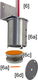
[6] | Signal generator | |
[6a] | Metal casing | |
[6b] | Signal generator: glass thermobulb | |
[6c] | Signal generator: compression spring |
|
[6d] | Signal generator: lid |
|